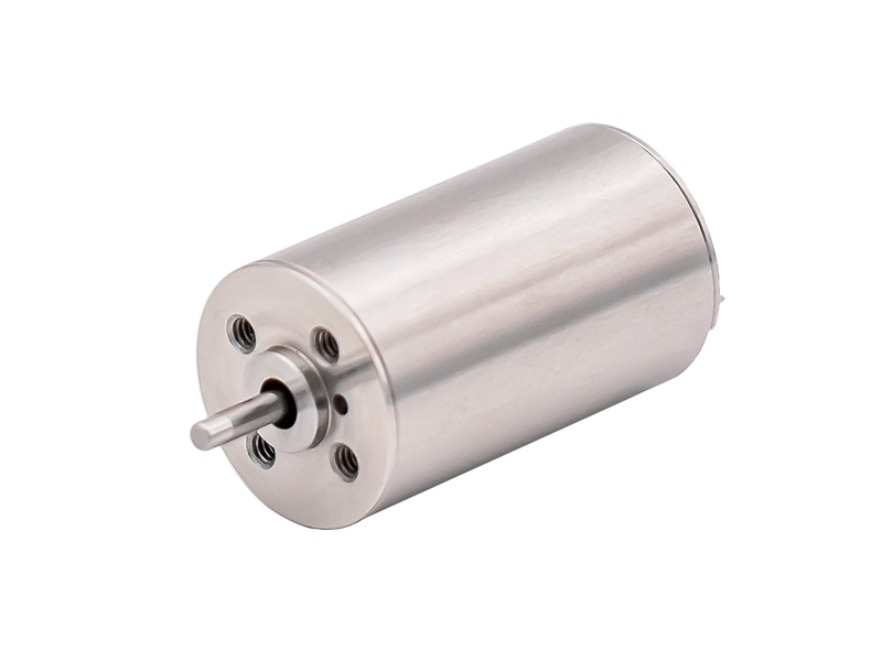
These 44 common sense tips help you better understand brushless DC motors (Part 2)
23.In a motor, leakage flux refers to the magnetic flux generated only by the winding itself, and the back electromotive force generated can often be equivalent to a leakage voltage reduction (or negative voltage reduction).
24. There are two types of rotors for asynchronous motors: squirrel cage and wound rotor.
25. The slip rate s of an asynchronous motor is defined as the ratio of the difference between the synchronous speed and the rotor speed to the synchronous speed. When an asynchronous motor operates in the motor state, the range of its slip rate s is 1>s>0.
26.The Tem-s curve of the electromagnetic torque Tem and slip rate s of asynchronous motors has three key points, namely the starting point (s=1), the maximum electromagnetic torque point (s=sm), and the synchronization point (s=0). When the rotor resistance of an asynchronous motor changes, the magnitude of its maximum electromagnetic torque Tem and the characteristic of the slip rate sm are: the magnitude remains unchanged, while the position of s changes.
27. Asynchronous motors must absorb reactive power with hysteresis properties from the power grid for excitation.
28. When an alternating current is applied to a coil assembly, its magnetic potential exhibits pulsating properties over time. When a single coil is subjected to alternating current, its magnetic potential also exhibits pulsating properties over time.
When a synchronous generator is connected to the grid, it is required that its three-phase terminal voltage has the same frequency, amplitude, waveform, phase sequence (and phase) as the three-phase voltage of the grid.
30. There are two types of rotors for synchronous motors: hidden pole and salient pole.
31. The equivalent number of phases of the squirrel cage rotor is equal to its number of slots, and the equivalent number of turns for each phase is 1/2.
32. Three phase symmetrical AC winding, passing symmetrical three-phase AC current, its fundamental synthesized magnetic electromotive force is a circular rotating magnetic electromotive force, and its rotation direction is from the axis of the leading phase winding to the axis of the lagging phase, and then to the axis of the next lagging phase.
33. There are two connection methods between the three-phase windings of a three-phase transformer: star and triangle; There are two types of magnetic circuits: group type and center type.
34. The six odd numbered connection groups of the three-phase transformer are numbered 1, 3, 5, 7, 9, and 11. And the six even connected group numbers are 0, 2, 4, 6, 8, and 10.
In the AC winding, the number of slots per pole and phase is q=q=Z/2p/m (assuming the number of slots is Z, the number of pole pairs is p, and the number of phases is m). In AC windings, both 120o and 60o phase belts are used. The fundamental winding coefficient and back electromotive force of the 60o phase band are relatively high.
36. The symmetrical component method can be used to analyze the asymmetric operation of transformers and synchronous motors. The prerequisite for its application is that the system is linear, so the superposition principle can be applied to decompose the asymmetric three-phase power system into three symmetrical three-phase systems: positive sequence, negative sequence, and zero sequence.
The formula for calculating the short distance coefficient is ky1=sin (p/2 × y1/t), which physically means the discount (or reduced coefficient) of the back electromotive force (or magnetomotive force) caused by short distance compared to the entire distance. The formula for calculating the distribution coefficient is kq1=sin (qa1/2)/q/sin (a1/2). Its physical meaning is the coefficient (or discount) that decreases when the back electromotive force (or magnetomotive force) is relatively concentrated when q coils differ by an electrical angle of a1 in sequence.
38. Current transformers are used to measure current, and their secondary side cannot be open circuited. Voltage transformers are used to measure voltage, and their secondary side cannot be short circuited.
39. A motor is a device that converts mechanical energy into electrical energy (or vice versa), or changes one AC voltage level to another. From the perspective of energy conversion, motors can be divided into three categories: transformers, electric motors, and generators. Brushless DC motors can also be classified into multiple categories based on different angles.
The calculation formula for the distance between slots and the electrical angle a1 is a1=p × 360o/Z. The visible slot distance electrical angle a1 is equal to p times the slot distance mechanical angle am.
The principle of transformer winding calculation is to ensure that the magnetic potential of the winding remains unchanged and the active and reactive power of the winding remain unchanged before and after calculation.
The characteristic of the efficiency characteristic curve of a transformer is the existence of a maximum value, which is reached when the variable loss equals the constant loss.
The no-load test of transformers is usually conducted by applying voltage and measuring on the low voltage side. The short-circuit test of transformers is usually conducted by applying voltage and measuring on the high voltage side.
When transformers are operated in parallel, the condition for no no-load circulating current is that the transformation ratio is the same and the connection group number is the same.