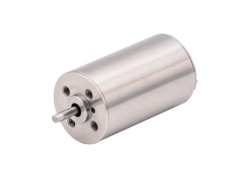
Do you know how brushless DC motors work?
Brushless DC motors have become very popular, and their applications may be more common than Wi Fi. Whether at home, in the office, or in surrounding scenarios such as cars, you may be surprised to find these brushless DC motors.
In yesterday's article, we introduced some professional terms about brushless DC motors; So, do you know how brushless DC motors work?
The rotation of a brushless DC motor or permanent magnet synchronous motor requires commutation of the driving signal applied to the stator winding. A semiconductor based motor drive controller (commonly referred to as a driver) generates waveforms, the number and shape of which depend on the type and number of phases of the motor.
Compared with the sinusoidal method with field oriented control (FOC) used in permanent magnet synchronous motors, brushless DC motors are suitable for trapezoidal driving waveforms. In three-phase PMSM, commutation utilizes three sine wave waveforms that are 120 degrees out of phase with each other. BLDC motors can also be driven using sine waves.
Whether using FOC or trapezoidal drives, effective rotor control requires precise knowledge of the position of the rotor relative to the stator winding, which can provide important feedback for motor drive to better control motor speed and torque. The position information determines the order, time, and frequency of the driving signal.
There are two methods to determine the position of the rotor: sensor or sensorless.
Sensor: Hall effect sensors can be placed next to each stator winding (see the blue square in Figure 2), which can detect changes in magnetic field polarity (N to S, S to N) when the rotor rotates. Each three-phase motor requires three sensors.
Sensorless: The sensorless method uses back electromotive force to determine rotor position instead of using sensors.
Both sensing methods have their own advantages and disadvantages. The use of Hall effect sensors involves additional component costs and more assembly time, but BLDC/PMSM motors using sensor sensing can provide excellent torque, smooth rotation, and higher efficiency. The drive controller of permanent magnet synchronous motor is often more complex, and using FOC requires the use of sensors.
The sensorless method is common in brushless DC motors, which can achieve a relatively attractive low price, but requires the algorithm to determine the rotor position based on the back electromotive force induced in the stator winding. A major challenge of sensorless BLDC motors arises during startup, where there is no back electromotive force due to the absence of any motion, requiring a different method for calculating the rotor position. Usually, high-frequency driving signals are fed to each phase winding and the position is calculated accordingly through specific algorithms.
Simplified diagram of three-phase BLDC motor, in which Hall effect sensors are used to create commutation process and inverter operations are sorted (source: Qorvo)-
The above figure highlights a simple three-phase BLDC motor configuration using Hall effect sensors (HSW, HSV, and HSU). Sensors are basically digital switches that indicate the polarity of the detected magnetic field, with N equal to "1" and S equal to "0". The outputs of three sensors are combined to provide a 3-digit logic "opcode" that indicates the position and direction of the rotor when it changes. This information is the basis for the driving signal provided by the three-phase power transistor inverter stage.
For BLDC applications with relatively low power, sensor interfaces, motor controllers, and drive transistors are typically integrated into a single controller IC. High power motors typically use gate drive outputs from controller ICs and power MOSFETs equipped with heat sinks to achieve the required drive current.
To change the speed of the motor, pulse width modulation (PWM) technology can be used to adjust the duty cycle, which is the ratio of pulse on/off. This method can limit the starting current, thus providing significant advantages when used during motor start-up.
Keywords: