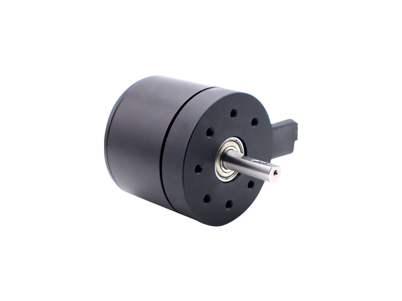
DC brushless motor: control method for suppressing commutation torque fluctuation.
When working on a brushless DC motor, it can cause commutation torque fluctuations. How to suppress torque fluctuations? Below, the editor will introduce several methods to suppress torque fluctuations caused by current commutation.
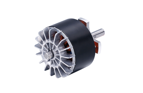
Current feedback regulation method
As mentioned earlier, the fluctuation of non commutation phase current leads to commutation torque fluctuation. The current feedback regulation method is to keep the commutation phase current constant, so as to make the commutation torque fluctuation zero. Generally speaking, current feedback control can be divided into two forms, namely DC side current feedback control and AC side current feedback control. The current feedback signal of the DC side current feedback control is extracted from the DC bus and mainly controls the amplitude of the current. Since the DC side current feedback control is based on the current signal flowing through the DC power supply, only one current sensor is needed. The current feedback signal of the AC side current feedback control is extracted from the AC side. At this point, determine the phase current to be controlled based on the position of the rotor, so that it follows the set current value command. During the commutation process, when the non commutation phase current does not reach the set value, PWM control does not work; When the non commutation phase current exceeds the set value, PWM control begins to take effect, causing the current value to decrease, achieving regulation of the non commutation phase current and maintaining stability.
In current feedback closed-loop control, hysteresis current control method is commonly used. The basic principle is that the current loop adopts a loop current regulator. By comparing the set current with the actual current, the output of the hysteresis current regulator control signal is determined by the amplitude of the actual current and the size of the hysteresis width. When the actual current is less than the lower limit of the hysteresis width, the switching device conducts; As the current increases and reaches the upper limit of the hysteresis width, the switching device turns off, causing the current to decrease. The actual current can be the phase current or the bus current of the inverter.
The characteristics of hysteresis current method are: simple application, good speed, and current limiting ability.
There are three types of hysteresis current control methods: those controlled by rising phase current, those controlled by non commutation phase current, and those independently controlled by three-phase phase current.
The experimental results comparing the effectiveness of these three methods in suppressing commutation torque fluctuations demonstrate that the commutation torque characteristics of the latter two cases are the same. It has a good suppression effect on commutation torque fluctuations and is suitable for low speeds. The control strategy of reducing electromagnetic torque during commutation by directly controlling the non commutation phase current through hysteresis control during commutation. According to the fact that the electromagnetic torque during commutation is proportional to the non commutation phase current, and the reference value of the non commutation phase current is constant, after determining the non commutation phase current to be controlled and the corresponding reference current, the phase current is controlled by a hysteresis comparator to ensure that the non commutation phase current follows its reference value during commutation, which can effectively reduce the fluctuation of electromagnetic torque during commutation. The control method mentioned in the article has small torque fluctuations and a simple and easy to implement circuit. Compared to traditional three-phase hysteresis control, it has the characteristics of low power transistor losses and high efficiency, making it very suitable for high-performance servo drive systems.
Another method based on controlling commutation current. This method takes the commutation current as the research object, and maintains the stability of the current during commutation by making the decrease rate of the turn off phase current equal to the increase rate of the turn on phase current, thereby reducing torque fluctuations. During the commutation period, by applying appropriate compensation voltage to the winding faces of phases A and C, the current of phase C is kept constant to suppress torque fluctuations. The experimental results show that this method achieves good results in the application of subway platform screen doors, reducing current fluctuations by 8% and torque fluctuations by 10%.
Overlapping commutation method
Although the current feedback method and hysteresis current method have solved the torque fluctuation problem of low-speed commutation, their effects are usually not ideal at high speeds. The mature method for suppressing commutation torque fluctuations in high-speed sections is the overlap commutation method. The basic principle is that the power switching device that should be turned off immediately during commutation is not turned off immediately, but rather an extended time interval; Turn on the switch devices that should not be turned on yet in advance. In the traditional overlap commutation method, the overlap time needs to be predetermined, but selecting an appropriate overlap time is difficult. If it is too large, it will overcompensate, and if it is too small, it will cause insufficient compensation. Therefore, based on the conventional overlapping commutation method, fixed frequency sampling current regulation technology has been introduced. This technology uses PWM control to suppress commutation torque fluctuations during the overlap period, allowing the overlap time to be automatically adjusted by the current regulation process, thereby avoiding the problem of difficulty in determining the size of the overlap interval. However, this method must ensure a sufficiently high current sampling frequency and switching frequency to be effective. In addition, although this method is effective in suppressing commutation torque fluctuations at high speeds, it requires offline solution of switch states and the algorithm is complex, which has certain limitations in practical applications.
PWM chopping method
The hysteresis current method effectively solves the problem of commutation torque fluctuation at low speeds, but the effect is not ideal at high speeds. The PWM new wave method is similar to the AC side current feedback control method, in which the switching device performs a certain frequency chopping before disconnection and after conduction to control the terminal voltage of the winding during the commutation process, so that the rate of rise and fall of each commutation current is equal, compensating for changes in the total current amplitude and suppressing commutation torque fluctuations. Compared with the overlapping commutation method, this method has smaller torque fluctuations and is suitable for situations with higher accuracy requirements.
Current prediction control method
The commutation torque fluctuations of DC brushless motors are different in high-speed and low-speed regions, and most research on suppression methods considers them separately. However, in practical applications, due to factors such as motor speed and supply voltage, it is difficult to divide the commutation torque fluctuation into high-speed and low-speed regions and adopt different suppression measures as theoretically analyzed. Therefore, it is necessary to seek a method that can effectively suppress commutation torque fluctuations across the entire speed range. The current prediction control method meets this requirement. It takes the commutation current as the research object and derives the predictive control rules for the commutation current of the motor during high-speed and low-speed operation, ensuring that the current drop rate of the turn off phase and the current rise rate of the turn on phase are equal during commutation, thereby keeping the phase current of the non commutation phase winding constant during commutation and reducing commutation torque fluctuations. At the same time, the method combines the elimination of negative DC bus current to further suppress commutation torque fluctuations. The commutation current prediction control method has a simple algorithm, easy implementation, strong adaptability, and obvious effect. It can be well embedded into the commutation period in open-loop control, traditional current PI control, and control systems using modern intelligent control algorithms, effectively suppressing commutation torque fluctuations.
Direct torque control method
The torque direct control method adopts a two-phase conductive method without coordinate transformation, and considers the limited power supply capacity of the DC power supply during the winding commutation period. During commutation, when the duty cycle of the switching transistor corresponding to the rising phase winding reaches 100%, if there is still torque fluctuation, the switching transistor corresponding to the falling phase winding is turned on for chopper control to reduce the rate of decrease of the falling phase current, and the duty cycle of the switching transistor can be calculated. Simulation and experimental results show that this method can effectively suppress the torque fluctuation of non ideal back electromotive force brushless DC motors. This method is only applicable in situations where the speed change is not significant.
Torque closed-loop control method
In recent years, torque closed-loop control methods have been proposed to address torque fluctuations. It takes the instantaneous torque of the motor as the control object, and based on the actual torque feedback signal, directly controls the instantaneous torque through a torque regulator to reduce torque fluctuations. If feedback signals are provided through torque sensors, the system response will be slow and mostly can only operate in static or low-speed states. If a torque observer is constructed by utilizing the structural parameters of the motor and some easily measurable state variables, the operation will be quite complex, and parameter changes will also bring certain errors. These issues still need to be improved and resolved.