How to choose the appropriate driving motor for mobile robots?
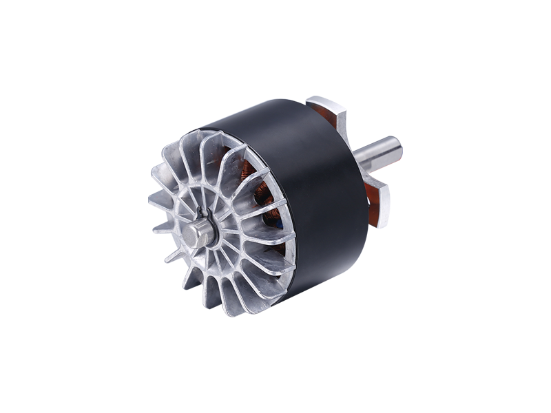
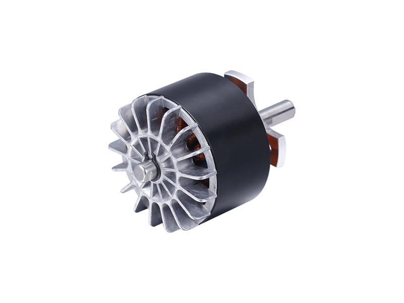
In mobile robots, the function of the driving motor is to convert electrical energy into angular displacement, angular velocity, or torque of the motor shaft for mechanical energy output under the action of control signals such as voltage, current, pulses, etc. The structure of a drive motor generally includes: base, housing, front and rear end caps, stator components, rotor components, iron core, insulated winding, motor shaft, bearings, commutator, encoder, brake device, etc. The commonly used driving motors for mobile robots include DC servo motors, AC servo motors, and stepper motors. Below, we will introduce each one in detail:
1、 DC servo motor
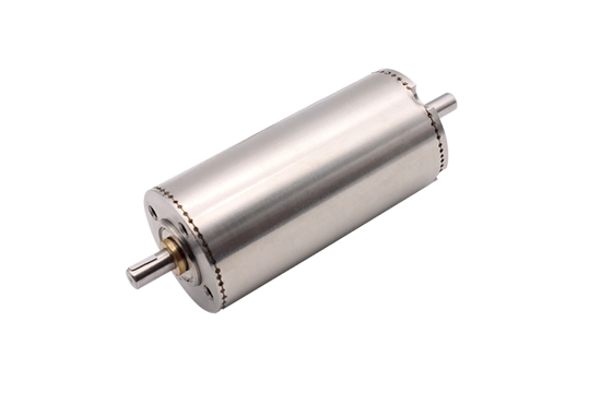
DC servo motors are powered by DC power supply, including ordinary DC servo motors, disc-shaped armature DC servo motors, hollow cup armature DC servo motors, slotless armature DC servo motors, DC torque motors, etc.
The basic working principle of a DC servo motor is exactly the same as that of a regular DC motor, which generates electromagnetic torque through the action of armature current and air gap flux, thereby causing the stator of the DC servo motor to rotate. DC servo motors usually use armature control method, which adjusts the speed by changing the armature voltage while keeping the excitation voltage constant: the smaller the armature voltage, the lower the speed; When the armature voltage is zero, the motor stops.
Mobile robots generally carry their own batteries, so the driving motors used are mainly DC servo motors. When the voltage of the DC servo motor is inconsistent with the battery voltage, it is necessary to use a power conversion module (DC-DC) to achieve adaptation between the two.
1. Ordinary DC servo motor
The stator of a regular DC servo motor is electromagnetic or permanent magnet, and the rotor is composed of a slotted iron core and an armature winding embedded in the slot. Ordinary DC servo motors have strong load capacity and large locked rotor torque, but due to the complex rotor structure and large volume, the mechanical inertia of the motor is large, resulting in poor stability at low speeds and a large control dead zone.
2. Disk shaped armature DC servo motor
The stator of a disc-shaped armature DC servo motor is permanent magnet type, and the rotor is a disc structure. The armature can be divided into wire wound type (wire wound disc type) and printed circuit type (printed disc type). The motor has a simple structure, small size, and light rotor weight. The mechanical inertia of the rotor is small, but the blocking torque is small. The capacity of a wire wound disc motor can reach several kilowatts, while the capacity of a printed disc motor is smaller.
3. Hollow cup armature DC servo motor
The stator of the hollow cup armature DC servo motor is a permanent magnet type, and the rotor is composed of a hollow cup structure as the skeleton, on which the armature winding is placed (or printed) on the cup wall. The armature winding can be a wound winding or a printed winding. This servo motor is known for its extremely small mechanical inertia, high control sensitivity, almost no control dead zone, and can be made very small in size and lightweight. But the blocking torque is relatively small, and currently its capacity cannot be made very large. It is a type of miniature servo motor.
4. Slotless armature DC servo motor
The only difference between a slotless armature DC servo motor and a regular DC servo motor is that its rotor iron core is not slotted, and the armature winding is fixed with adhesive on the surface of the armature. This type of servo motor has a large load capacity, a large locked rotor torque, a large motor capacity, and good low-speed stability.
5. DC torque motor
DC torque motor is a low-speed, high torque motor that can directly drag the load to achieve smooth operation at low speed and high torque without the need for an intermediate reduction mechanism. It can even work in locked rotor conditions without crawling, and has high speed stability accuracy. Therefore, it is particularly suitable for situations with lower speeds and considerable load capacity requirements. DC torque motors have the same structure as ordinary DC servo motors, but they have more main magnetic poles in the stator and are usually made into a flat structure. The following figure shows a DC torque motor used for the joints of a certain type of quadruped robot.
2、 Communication servo motor
AC servo motors are powered by AC power supply, including synchronous AC servo motors and asynchronous AC servo motors.
AC servo motors are structurally similar to single-phase asynchronous motors, with two-phase windings placed in the stator core with a spatial difference of 90 ° electrical angle, one phase being the excitation winding and the other phase being the control winding. When the electric motor is working, the excitation winding is connected to a single-phase AC voltage, and the control winding is connected to a control signal voltage, requiring that the two-phase voltages have the same frequency. There are two structural forms of rotors for AC servo motors: cage rotors and hollow cup rotors. The application of AC servo motors in industrial robots is relatively common, while their application in mobile robots is relatively rare.
1. Asynchronous AC servo motor
Asynchronous AC servo motor refers to AC induction motor, which can be divided into three-phase and single-phase, as well as squirrel cage and wire wound types. Squirrel cage three-phase induction motor is usually used. Its structure is simple, and compared with DC motors of the same capacity, it is 1/2 lighter in weight and only 1/3 of the price of DC motors. The disadvantage is that it cannot achieve a wide range of smooth speed regulation.
2. Synchronous AC servo motor
The stator of synchronous AC servo motors, like asynchronous motors, is equipped with symmetrical three-phase windings on the stator. But the rotor is different, and it can be divided into two categories according to different rotor structures: electromagnetic and non electromagnetic. Non electromagnetic types are divided into hysteresis, permanent magnet, and reactive types. Hysteresis and reactive synchronous motors have disadvantages such as low efficiency, poor power factor, and small manufacturing capacity. The advantages of permanent magnet type are simple structure, reliable operation, and high efficiency, while the disadvantages are large volume and poor starting characteristics.
3、 Stepper motor
A stepper motor is a type of electric motor that converts electrical pulse signals into corresponding angular or linear displacements. There are many structural forms and classification methods for it, generally divided into three types according to the excitation method: reluctance type, permanent magnet type, and mixed magnet type; According to the number of phases, it can be divided into single-phase, two-phase, three-phase, and multi-phase forms. The operational performance of stepper motors is closely related to their control methods. From the perspective of their control methods, stepper motor control systems can be divided into the following three categories: open-loop control systems, closed-loop control systems, and semi closed loop control systems.
A stepper motor is a type of electric motor that converts electrical pulse signals into corresponding angular or linear displacements. Every time a pulse signal is input, the rotor rotates one angle or advances one step, and its output angular displacement or linear displacement is proportional to the number of input pulses, and the speed is proportional to the pulse frequency. Therefore, stepper motors are also known as pulse motors. The characteristic of stepper motors with only periodic errors and no cumulative errors has made them widely used in industries, aerospace, robotics, precision measurement, and other fields. Stepper motors are generally used in robot systems that do not require high precision and speed.
The working principle of a stepper motor is that when current flows through the stator winding, the stator winding generates a vector magnetic field. The magnetic field will drive the rotor to rotate by an angle, so that the direction of the rotor's pair of magnetic fields is consistent with that of the stator's magnetic field. When the vector magnetic field of the stator rotates by one angle, the rotor also rotates by one angle with the magnetic field. For every input of an electrical pulse, the motor rotates one angle and advances one step. The angular displacement output is proportional to the number of pulses input, and the rotational speed is proportional to the pulse frequency. Changing the order of winding electrification will cause the motor to reverse. So the rotation of the stepper motor can be controlled by controlling the number and frequency of pulses, as well as the sequence of energizing each phase winding of the motor.